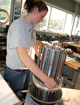
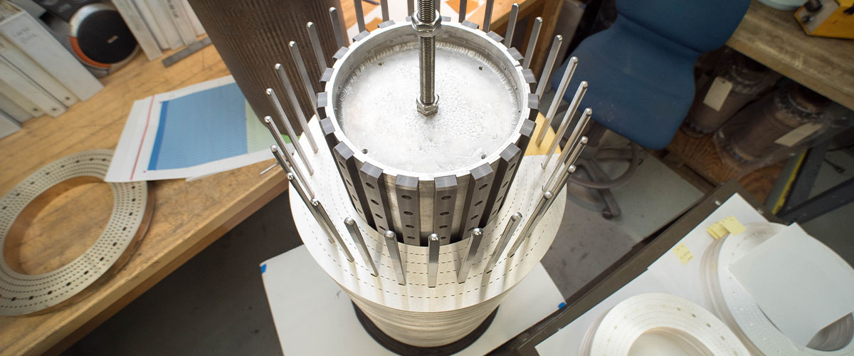
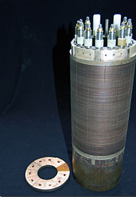
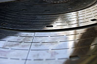
A resistive magnet coil.
The National High Magnetic Field Laboratory is home to dozens of powerful magnets. Each year the world-record instruments attract hundreds of scientists from as far off as Japan, Australia and Europe. Scientists come from across the globe to put their experiments inside these magnets and see what happens when materials are subjected to high fields.
But the MagLab doesn't just conduct research with magnets. We also make magnets, both for our own lab and for other labs around the world.
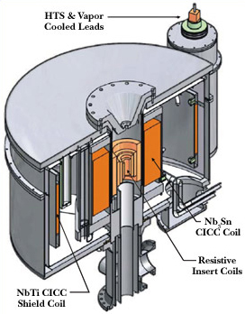
We make all kinds of magnets, including superconducting, hybrid and pulsed magnets. We're world leaders in creating all these magnets.
But in this article, we'll focus on how we make resistive magnets, a type of electromagnet, which use conventional electricity to generate high magnetic fields. Experts in our Magnet Science and Technology division are renowned for their ability to design and construct these tools. They have created 13 different magnet designs and have built dozens of these magnets over the years, requiring the construction of some 160 magnet coils.
Harnessing electrons
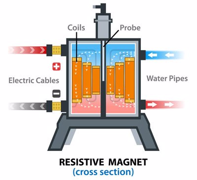
First off, a quick explanation of what a resistive magnet is. It bears no resemblance to the things sticking to your refrigerator. Those are a different class of magnet altogether, called permanent magnets, made of alloys like Alnico – a combination of aluminum, nickel and cobalt. Due to the nature of those materials, they have a permanent but weak magnetic field. Our most popular magnets are resistive magnets, a type of electromagnet, which create magnetic fields using electricity. Unlike permanent magnets, electromagnets can be switched on and off. They can be very simple – you can make a basic electromagnet at home strong enough to pick up paper clips. But you can (and we do) make them a lot stronger, largely by pumping in more and more electricity.
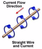
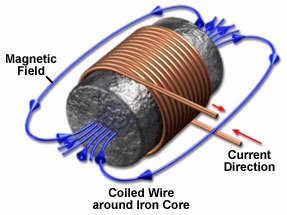
In a nutshell, this is how they work. Electrons traveling through a wire (i.e., electricity) generate a magnetic field around them as they move, as shown below.
If you take that wire and coil it, you concentrate a lot of field in the center.
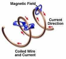
If you coil a wire twice, three times, a hundred times into a shape called a solenoid, you get an ever stronger field in the center area.
That's essentially the idea behind our resistive magnets, except that instead of wires, we use flat copper plates, or discs, piled one atop the other. The fabrication and stacking of the plates are designed to maximize the amount of electricity they carry (the greater the current, the greater the magnetic field it generates) while minimizing the chance that electrical heat will melt the plates and ruin the magnet.
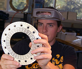
Inspecting a bitter disc.
These discs are the building blocks of our magnets; it takes hundreds of discs to make one magnet. The tiniest flaw in any one of these could impair the magnet or result in a costly malfunction.
So quality control is an obsession in the MagLab's Resistive Magnet Shop, where the coils are made. Every plate is checked, double-checked, and checked again throughout the magnet building process. Some very patient, persnickety perfectionists work in that shop.
"It's tedious," magnet technician Nicole Walsh readily concedes, "but if you realize that every single disc matters, then it just goes by faster."
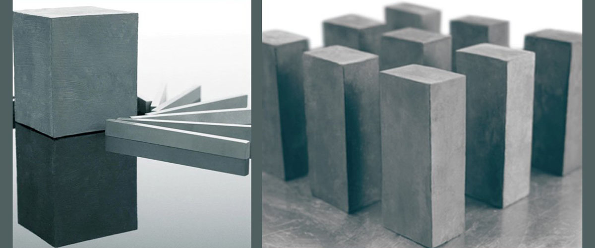
Ingredients: Only the best
Every plate that goes into our coils starts out life as a sheet of metal no thicker than a millimeter. Depending on the specifications of the magnet, the sheet may be made of pure copper, an excellent conductor, or of a copper alloy – copper-beryllium, copper-zirconium or copper-silver.
Of course, the first thing we do with this material is test it: Quality control dictates this process right from the get-go. Engineers in our Materials Characterization Lab scrutinize each incoming batch of metal for conductivity and strength.
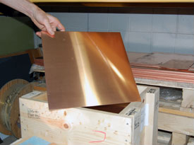
Raw material for a magnet.
The material has to be tough. It's going to take a licking and it needs to keep on ticking. The material will be subject to millions of pounds of pressure and power densities of 14 watts per cubic millimeter – more than in any other man-made device, according to Magnet Science & Technology Director Mark Bird.
"It is a little bit tricky because it's sheet metal, and they need to know the strength of it pretty accurately," explained MagLab engineer Bob Walsh, who developed and oversees the testing process. "The material can't have imperfections, it has to be made very well, and that way its strength is very consistent." The testing is an important first step in quality control. "We don't pay until we get this result," Walsh noted.
If the sheets pass muster, they're shipped off to an outside facility where pancake-like discs are cut out of them, each with a very particular pattern of round and elongated holes.
The Hole Story
There is quite a bit of science and engineering that goes into determining the precise size, shape, number and pattern of holes on any particular plate, which vary from magnet to magnet.
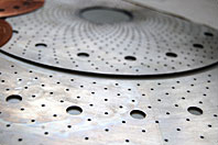
Old-style bitter plate.
The larger, round holes accommodate rods that are used to keep the plates in place as they are stacked one on top of the other. There is no wiggle room: Wiggling could translate into blocked holes, and blockages, as we will see, could trigger a meltdown.
The narrower, elongated holes prevent the plates from melting. They do this by funneling vast amounts of cold water right through the magnet, made quite hot by tremendous amount of current (we're talking megawatts). Were it not for the cold water rushing through at the rate of up to 15,000 liters (4,000 gallons) a minute, our magnets would quickly melt into copper puddles. (Deionized water is used to cool the magnets; unlike tap water, it contains no salt or other impurities, and therefore won't conduct electricity).
Florida bitter plate.
An MIT physicist named Francis Bitter came up with the idea for these holes back in the 1930s, an innovation that made more powerful magnets possible. That explains why the plates are commonly called Bitter plates. Back in Bitter's day, these water holes were round. But in the mid-1990s, MagLab engineers figured out that using elongated rather than round holes, and staggering rather than aligning the rows of holes, would greatly increase the coil's ability to withstand stress, meaning even more current could be pumped through the magnet resulting in a higher magnetic field – an incredible 40 percent increase in efficiency. Prior to this innovation, 20 megawatts of power could generate a field of 28 tesla (tesla is a measure of magnetic field strength – a fridge magnet, by comparison, is a mere .03 tesla). But since the invention of the Florida Bitter plate, that same 20 MW could yield 35 tesla.
The MagLab's Florida Bitter plate was quickly adopted by magnet makers worldwide; the design paved the way in 1995 for the lab's world-record 30 tesla resistive magnet. This was surpassed in 2005 by our 35 tesla resistive magnet, which remains one of most powerful magnets of its kind on earth. The secret in designing these holes is to find the right balance between the amount of copper used (maximizing the current) and the amount of copper sacrificed to the cooling holes (preventing a melt-down).
Every plate within a coil is identical, and they are stacked in such a way as to create within the coil dozens of very narrow tubes through which cold water can be flushed.
The above statement is 90 percent true. Here we must make a small detour to account for that other 10 percent and explain the Lorentz Force.
Forces to be reckoned with
Heat isn't the only devil in the details of resistive magnet design.
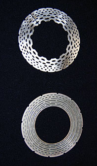
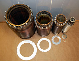
End-turn (top) and mid-turn discs.
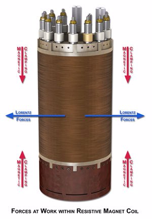
Inside any magnet coil, there are really two levels of magnetic fields. There's the larger field of the magnet generated by the multiple megawatts of power surging through it, and there are the much smaller fields generated by each of the countless electrons in motion. When these smaller fields interact with the larger field, a force (called the Lorentz force) is exerted, which pushes the plates outward. This isn't a problem in the middle of the coil (more on that in a minute), but it is at the top and bottom.
Because of this, holes in the top and bottom plates must be a bit wider so that they don't plug up the flow of cooling water when they shift out of alignment with the middle plates.
The middle plates have a secret weapon to counter the Lorentz force: magnetic clamping. This happens when wires (or in this case, coils) conduct current in parallel. (Our interactive tutorial on parallel wires illustrates this phenomenon). The direction of magnetic fields circling around these wires or coils is such that they attract each other. So discs in the middle of the coil attract each other like opposing magnets. This keeps the discs clamped together, even as the Lorentz force tries to force them outward, as illustrated below. Because magnetic clamping isn't strong at the ends of the coil, the Lorentz force can only be dealt with by making those holes wider.
MagLab engineers were the first to figure out how best to design around the interacting forces of magnetic clamping and the Lorentz force, giving them a 10 percent increase in efficiency. This advance occurred in 2000 while engineers were trying to set a new record of 45 tesla with our hybrid magnet (part superconducting magnet, part resistive magnet). The innovation of wider holes at the ends of the coils helped them achieve this goal.
Slow burr
When the stamped Bitter plates return to the MagLab, the magnet makers must battle the bane of their existence: burrs.
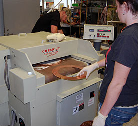
A machine deburrs plates.
Sticklers for details, the shop's technicians seek to eliminate every little bump, ragged edge and other imperfection left behind by the stamping process. Donning plastic gloves, they send every single plate, one at a time, through a very whiny deburring machine, which works something like a planer in a woodshop, smoothing out rough spots. Then they flip each plate over and send it through the machine again. For a typical coil, this process takes several days. Patience, sharp eyes and a pair of earplugs come in handy.
What's next? More quality control! Any holes still plugged? Any uneven spots? Any foreign materials accidentally stamped into the discs? Discerning eyes check for all possible problems.
All clean and shiny and smooth, the deburred, inspected plates are then shipped out for a high-class coating of silver. Like copper, silver is a great conductor of electricity. But unlike copper, it's a soft metal, so it conducts electricity better at those points where discs touch each other.
What happens when those pretty silver plates come back? You guessed it: more deburring. Each plate is inspected yet again and any offending burrs are manually smoothed away.
Stacking up
With all the plates finished and in tip-top shape, it's time to assemble them into a tower.
On its journey from the top of the magnet coil to the bottom, an electrical current wants to find the shortest, quickest route. That would not make for a very powerful magnet, however, so the coil stacking process is designed to make sure the current takes the longest possible path from point A to point B without melting the magnet. The idea is to have the current travel all around one loop, then move to the next loop, go all around it, then move to the next one, etc., etc., until the current has spiraled all the way up or down the coil. No shortcuts allowed.