The National High Magnetic Field Laboratory is home to some of the strongest magnets on the planet. The DC Field Facility at our Tallahassee, Florida, headquarters, which houses just a portion of our magnets, boasts several world-record holders alone, including the awesome 35-ton, 45 tesla hybrid magnet, which produces the highest sustained magnetic field of any magnet, anywhere.

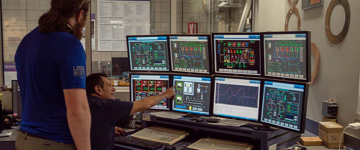
In the Control Room of the lab's DC Field Facility.
It’s like a team of world-class athletes — Team Tesla, we’ll call them, tesla being the unit of measure of magnetic field strength. (The Earth’s magnetic field is one twenty thousandth of a tesla.) They have an awful lot of power, but to stay in that kind of shape, they need to eat and drink — a lot.
And boy, do these athletes get fed; vast amounts of electricity and water are needed to keep them competitive. Think of the electricity we feed these magnets as an endless supply of PowerBars, and the water like a constant flow of Gatorade.
Behind any good team are outstanding trainers, and Team Tesla is no exception. These trainers staff the MagLab’s Control Room: Picture a smaller version of NASA’s mission control. There, 17 hours a day, highly specialized technicians surrounded by dozens of computer screens keep tabs on every inch of wire, every elbow of plumbing, every temperature reading and field measurement. Overseen by Magnet Operations Head Bryon Dalton, it is truly the brain of the lab, where all the data comes in and most of the day-to-day operational decisions are made.
Read on to learn how the lab has developed unique power and water systems to service these hungry all-stars.
Fire and ice
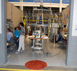
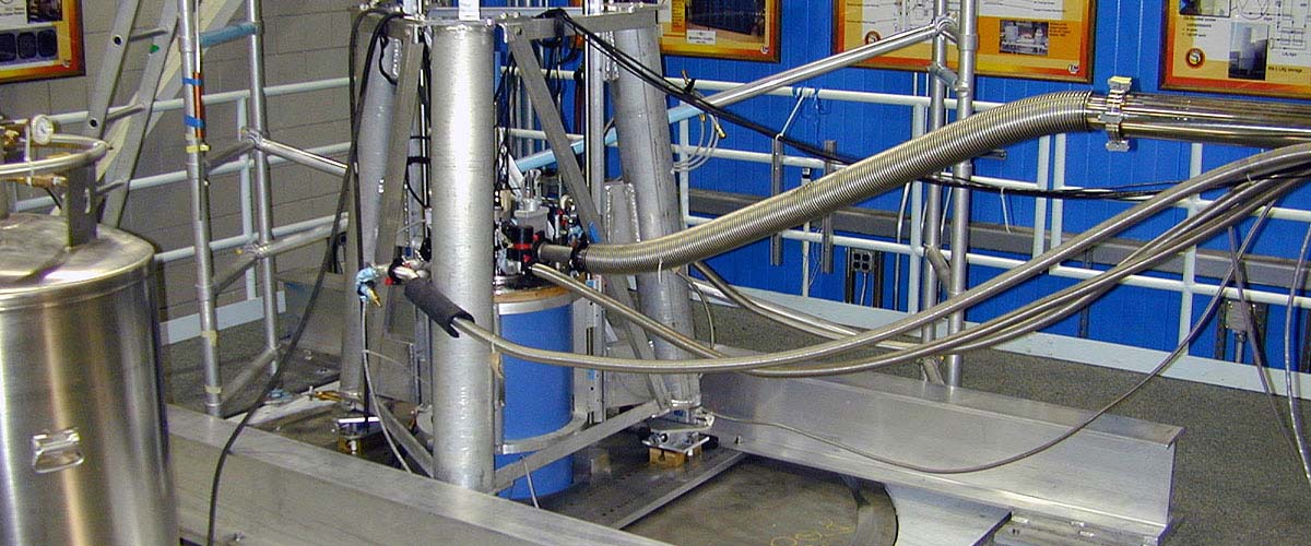
Scientists gather data from the world-record 36.2 tesla magnet, located at the rear of this "cell."
The story of how we power our magnets is a story of energy constantly changing form – fire to ice, electricity to magnetism, liquid to gas. As we follow the flow of energy through the Magnet Lab, keep in mind that handy first law of thermodynamics: Energy can be changed from one form to another, but it cannot be created or destroyed. All the energy that comes into the Magnet Lab also has to get back out.
Many of our magnets run on conventional electricity. These are called resistive magnets, which are largely housed in our DC Field Facility. (A number of powerful superconducting magnets are also found at the MagLab, but that’s another story.) This 72,000-square-foot wing of the lab contains eight resistive magnets (also called electromagnets or Bitter magnets), ranging in magnetic field from 25 tesla to 45 tesla, each in its own little “cell.” These magnets get so hungry they consume 7 percent of all the electricity used in the city of Tallahassee. The average monthly residential electricity consumption is about 920 kilowatt-hours (kWh). In 2010, the average monthly electricity consumption of magnets at the MagLab was the 3.8 million kwH.
That’s a lot of PowerBars. It all starts in an unassuming little building known as City of Tallahassee substation #31.
Pass the PowerBars
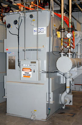
One of eight 28-ton transformers that convert the lab's 56 MW of electricity to a lower voltage.
One of eight 28-ton transformers that convert the lab's 56 MW of electricity to a lower voltage.Located near the MagLab, this substation draws electricity from the city’s power grid and distributes about 56 megawatts (MW) (or 56,000 kilowatts) to the lab. So at any given time, the lab has access to that amount of power. (By contrast, the typical load for U.S. home is a fraction of that – 2 to 4 kilowatts ). If we wanted to, we could turn on more than 800,000 60-watt light bulbs at once with that 56 MW. But since that would probably not do much to advance science, we run magnets with it, instead.
That power, in the form of 12,500-13,000 volts of alternating current (AC), travels from the substation to the lab’s power yard and main switchgear houses, where breakers distribute it to the lab’s electrical loads.
From there, eight 28-ton transformers take the current and step it down to a lower, more practical voltage. The transformers have two voltage taps, so the incoming 12,470 volts can be stepped down to either 520 or 640 volts (standard outlets in U.S. homes are 120 volts). Each of the transformers can distribute 7 MW of power, depending on the voltage.
Electricity, of course, comes from electrons traveling through wire conductors. The friction of all those electrons bumping into each other generates an enormous amount of heat – think how quickly a little ol’ 40-watt bulb can burn your finger. To keep these transformers from overheating, each is filled and cooled with 5,676 liters (1,500 gallons) of soybean-based dielectric oil, which doesn’t conduct electricity.

Current is carried to the magnets through 122 meters (400 feet) of solid aluminum bus bars.
By now the power is in the heart of the DC Field Facility. But it’s not ready to be fed to the magnets. If you haven’t guessed already from the facility’s name, that AC power, which works great in your home, needs to be converted to DC power (like what is used in a battery) for the magnets. AC power and resistive magnets are not a good combination; alternating current, as the name implies, flips direction some 60 times a second in the U.S. (50 times a second in Europe). The pole of a resistive magnet is determined by the direction of the current coursing through it. So if AC current was used with resistive magnets, their poles would flip every time the current flipped, making the magnets virtually unusable. How to rectify this situation?
 Conveniently enough, devices called rectifiers convert the AC to DC, creating a smooth, stable flow of power rather than the incessant fluctuations of AC. The current is divided among four power supplies, each of which can provide 14 MW of 700 volts DC. Each power supply can service only one magnet at a time. Since our weakest DC Field magnet requires 14 MW of power – enough to power more than 425 homes – no more than two of our resistive magnets can operate at the same time. (Also, we are limited to two magnets at a time because we only have two cooling loops). And when our biggest electricity hog, the 45-tesla hybrid magnet, is at full field, it draws on three of the power supplies, so no other DC Field magnet can run when the hybrid is in use (except for the energy-sipping Series Connected Hybrid Magnet. Magnet time must be scheduled so that demand for power never exceeds 56 MW.
To get from power supply to magnet, the DC current is conducted through solid aluminum bus bars located in the ceiling above the magnet cells. The current flows one way through one bus bar, and in the opposite direction through the other, creating a circuit between the power supply and each magnet, just like the circuit between the bulb and battery in your flashlight. The current direction through the magnet can be adjusted, depending on which way the researcher wants to orient the magnetic field.
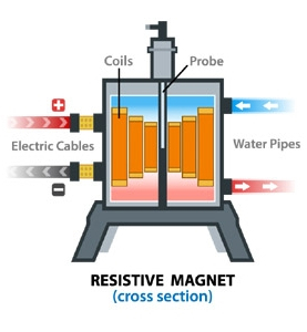
The current surges through the coils of the magnet, made up of hundreds of Bitter plates, pancake-like sheets of metal pocked with holes (we’ll explain those in a moment). The more current pushed through the coils, the greater the magnetic field produced. The field is most intense in the hollow center of the cylindrical magnet (called the bore), which is where scientists put their experiments, using a long, narrow tube called a probe.
Beverage break
So much for those PowerBars. Solids only account for half the magnets’ diet. With all that exertion, they need to keep up their fluid intake, too. And that’s where the magnet equivalent of Gatorade comes in.
Magnet water flows into the heat exchanger at 120 degrees Fahrenheit and exits at 42 degrees.
We’ve learned how massive amounts of energy, in the form of electricity, are pumped into the magnets. Now we will learn how all that energy – in the form of heat, or thermal energy – makes its way back out.
Three separate plumbing loops, totaling some 762 meters (2,500 feet) of pipe, tag team this task, helped by more than 35 pumps along the way. We’ll explain each loop in turn, starting with the hottest: The water coming right out of the magnet, the magnet-cooling system.
Any of our resistive magnets, on the receiving end of multiple megawatts, would quickly heat up to more than 1,000 degrees Celsius (almost 2,000 degrees Fahrenheit), melting into a copper puddle. That’s what would happen, anyway, if they weren’t cooled. So cold water is pumped right through the metal coils of the magnet, cooling it off as it heats up. To carry off the intense heat, the water rushes through the coils with three times the force of a fire hose: about 7,500 to 15,000 liters (2,000 to 4,000 gallons) of water per minute at pressures of 17 to 31 bar (250 to 450 pounds per square inch).
Sound like a recipe for electrocution? It might be, if the water came from the faucet. But this is deionized water: all the extra ions have been removed. Regular tap water conducts electricity – and would interfere with a magnetic field – because of those ions. Pure H20, however, does not. (Sadly, this fact messes with our Gatorade analogy, because that sports beverage is pumped full of electrolytes, thirst-quenching ions such as sodium and chloride). A water-treatment apparatus in this magnet-cooling system keeps the water deionized by passing it over a 60-cubic-foot bed of mixed resin, which draws off impurities.
Our four chillers could crank out two billion ice cubes a day.
After exiting the magnet, the water flows to one of two heat exchangers that, like the radiator in your car, transfer heat from one thing to another. In this case, the heat is transferred from the magnet cooling loop to the second water loop in this series – the chilled-water system. So magnet cooling water entering the heat exchanger at about 49 degrees Celsius (120 degrees Fahrenheit) exits at a much chillier 6 degrees Celsius (42 degrees Fahrenheit), then heads back to the magnet for its next cooling shift. Together, the heat exchangers can remove 56 MW of heat – the thermal equivalent of all the electricity coming into the DC Field Facility.
Two features work in parallel in the chilled water loop to keep the water cold: water storage tanks and chillers. Let’s talk about the tanks first.
Two, four-story water tanks behind the lab hold between them 16.3 million liters (4.35 million gallons) of water – the equivalent of about six and a half Olympic-size swimming pools. But you might not want to swim in them – the water is kept at 4.4 degrees Celsius (40 degrees Fahrenheit).
The volume of water in the tanks never changes; its purpose isn’t to water gardens or fill bathtubs, but to store thermal energy and make cold water available at a moment’s notice. Warm water enters at the top of the tank; cold is dispensed from the bottom. (Because this water does not come into contact with the magnets, it’s regular ground water – ions and all.) If only one smaller magnet is in use, these tanks are sufficient to keep the system cool. But with multiple or bigger magnets, the chillers kick in.
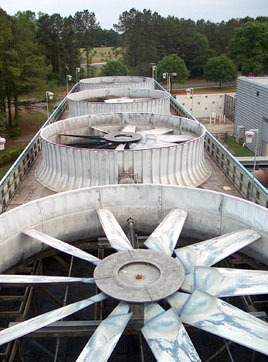
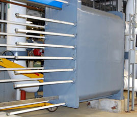
Energy that entered the lab as electricity exits as thermal energy through four cooling towers, evaporating into the atmosphere.
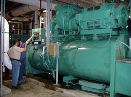
These are no household appliances; with a rating of 2,000 tons (a reference to chilling capacity, not weight), each of our four chillers is 400 times more powerful than a residential A/C system. If the lab was in the ice business, we could crank out 2 billion cubes a day. In fact, in addition to cooling magnet water, this system air-conditions the entire MagLab – no small feat during sultry Tallahassee summers.
Each 16.5-ton (as in weight) chiller puts about 3,625 kg (8,000 pounds) of refrigerant (R-22) through the same heat transfer cycle repeated (on a much smaller scale) inside your fridge dozens of times a day: it’s compressed, condensed, expanded and evaporated, drawing heat away from the warm water.
Thus the heat from the chilled-water system is transferred to the condenser-water system on the other side of the chillers. This water, at some 30 degrees Celsius (85 degrees Fahrenheit) now comfortably swimmable, is flushed into four cooling towers. Nine meters (30 feet) tall and stretching 44 meters (144 feet) along one side of the MagLab, these towers collectively can hold some 750,000 liters (200,000 gallons) of water. From here whatever energy is left in the water has nowhere to go but up … Up, up and away, coaxed by fans bigger than helicopter blades, into the atmosphere.
This is the end of our chapter on that 56 MW of energy that began at Tallahassee substation #31. But it’s not the end of the story. After all: Energy can be changed from one form to another, but it cannot be created or destroyed. The heat rejected into the atmosphere above the Magnet Lab will continue its adventures, onward and upward. Onward and upward, too, will go our knowledge of physics, biology, chemistry, materials science and engineering – thanks to experiments conducted in our powerful magnets.
Go, Team Tesla!
Resistive magnet operations diagram
Now that you've read all about how our DC Field Facility's world-record magnets are powered, take a virtual look at how the many components of this amazing system work together. Click on any of the question marks below for more information on individual components.
By Kristen Coyne